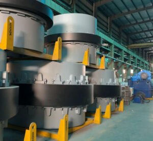
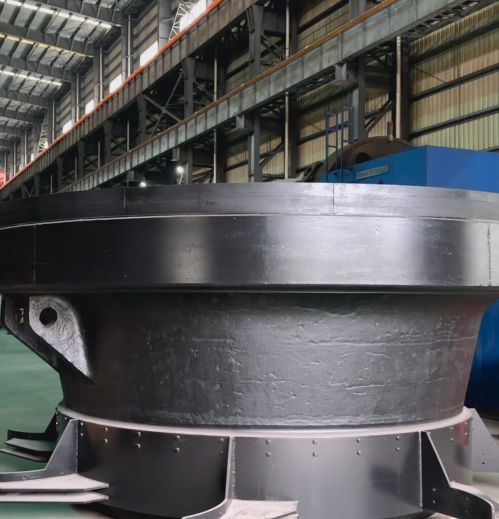
The grinding table disc of vertical roller mill is mainly used to support the material and cooperate with the grinding roller to complete the grinding operation. It is usually made of high-strength cast steel or steel plate welded together, and can withstand the strong pressure from the grinding roller and the long-term wear of the material. The surface of the grinding disc is covered with a high-wear-resistant alloy liner, and is equipped with a pressure block to fix the liner, a material retaining ring to prevent material overflow, a scraper to remove residual material, an air ring to form an annular air duct, and an air guide to guide the hot air flow. During the working process, the motor drives the grinding disc to rotate through the reducer, so that the material moves outward under the action of centrifugal force and is crushed under the grinding pressure of the grinding roller. At the same time, the hot air blown out by the air ring completes the drying and transportation of the material. The key functions of the grinding disc include supporting and evenly transmitting materials, providing a grinding working surface, guiding airflow and improving grinding efficiency.

We are the manufacturer
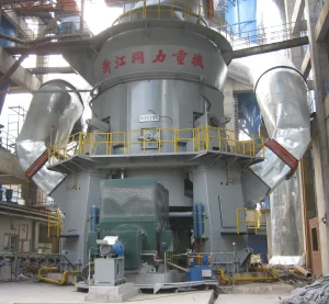
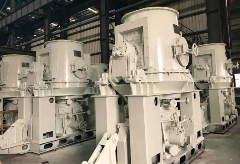
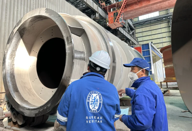
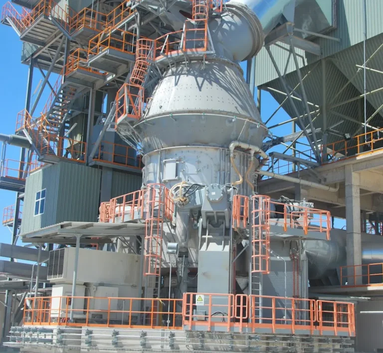
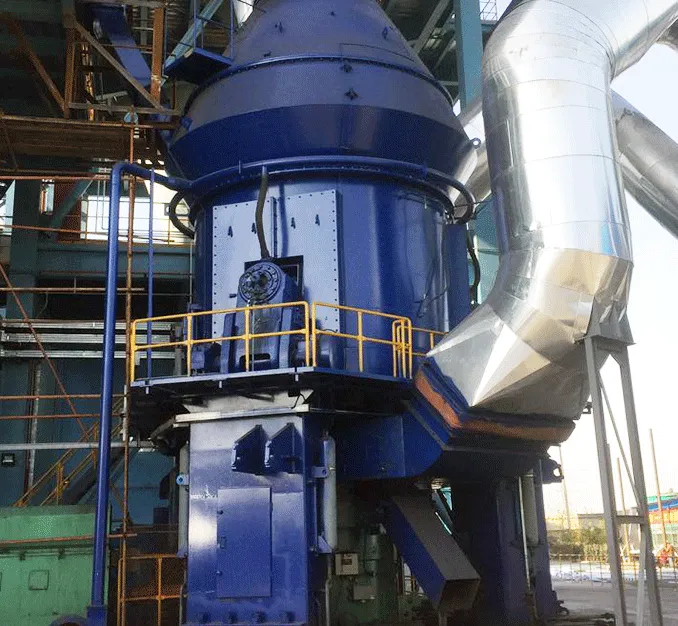
TONGLI-Vertical Roller Mill Accessories Expert
Tongli vertical mill grinding discs are made of heat-resistant steel materials containing alloy elements such as 15%-20% chromium (Cr) and 3%-5% molybdenum (Mo). After working continuously for 1000 hours at a high temperature of 350℃, its yield strength decreases by less than 8%, and its tensile strength remains above 90% of the standard value.
The surface of the grinding disc uses high-chromium cast iron such as KmTBCr26 and wear-resistant materials such as nickel hard alloys such as Ni-Hard4 as linings. The Rockwell hardness of KmTBCr26 can reach 58-65 HRC, and the Brinell hardness of Ni-Hard4 can reach 500-600 HB. With its extremely high hardness, it can effectively resist the scratching and erosion of materials during the grinding process. Under the same production conditions, the wear of the grinding disc is reduced by 60%-70% compared with ordinary liner materials, and the maintenance cost is greatly reduced. The replacement frequency of the liner is extended from once every 6 months to once every 18-24 months. The grinding efficiency is always stable at a high level, and the fluctuation range is controlled within ±5%.
In special production environments, facing materials containing corrosive components, the vertical mill grinding disc uses corrosion-resistant materials, such as austenitic stainless steel 304L containing 18%-20% chromium (Cr) and 8%-10% nickel (Ni). In an acid-base environment where the pH value of the material is between 2 and 12, the corrosion rate of the grinding disc surface is less than 0.1mm per year, which can effectively resist the erosion of corrosive substances such as acids and alkalis in the material, prevent the grinding disc surface from being corroded and damaged, always maintain the performance and structural integrity of the grinding disc, and ensure long-term stable operation.
Tongli vertical mill grinding discs often use high-strength cast steel materials such as ZG35CrMo. The yield strength of ZG35CrMo is ≥390MPa, the tensile strength is ≥650MPa, and the impact toughness is ≥35J/cm², with excellent strength and toughness. When the grinding disc rotates at a high speed of 50-80 revolutions per minute and interacts with the material and the grinding roller, it can withstand pressure and impact forces of up to 3000-5000N. Under normal working conditions, the grinding disc can ensure continuous and stable operation for more than 20,000 hours, which is 30%-50% longer than ordinary material grinding discs.
| Manufacturer | Model | Grinding Table Diameter (mm) | Capacity (t/h) | Main Application |
| Zhejiang Tongli (ZJTL) | ZJTL 1200 | 1200 | 10-15 | Cement, Raw Meal, Coal Powder |
| Zhejiang Tongli (ZJTL) | ZJTL 1500 | 1500 | 20-30 | Cement Raw Meal, Slag |
| Zhejiang Tongli (ZJTL) | ZJTL 1800 | 1800 | 30-50 | Cement Raw Meal, Slag |
| Zhejiang Tongli (ZJTL) | ZJTL 2200 | 2200 | 50-70 | Clinker, Slag |
| Zhejiang Tongli (ZJTL) | ZJTL 2500 | 2500 | 70-100 | Cement Clinker, Slag |
| Zhejiang Tongli (ZJTL) | ZJTL 2800 | 2800 | 90-120 | High Capacity Cement Raw Meal |
| Zhejiang Tongli (ZJTL) | ZJTL 3200 | 3200 | 120-150 | Cement Raw Meal, Slag |
| Zhejiang Tongli (ZJTL) | ZJTL 3500 | 3500 | 150-180 | Clinker, Slag |
| Zhejiang Tongli (ZJTL) | ZJTL 3800 | 3800 | 180-220 | Cement Clinker, Slag |
| Zhejiang Tongli (ZJTL) | ZJTL 4200 | 4200 | 220-250 | High Capacity Cement Raw Meal |
| Zhejiang Tongli (ZJTL) | ZJTL 4600 | 4600 | 250-300 | Cement Raw Meal, Slag |
| Zhejiang Tongli (ZJTL) | ZJTL 5000 | 5000 | 300-350 | Cement Clinker, Slag |
| Zhejiang Tongli (ZJTL) | ZJTL 5400 | 5400 | 350-400 | High Capacity Cement Raw Meal |
| Zhejiang Tongli (ZJTL) | ZJTL 5800 | 5800 | 400-450 | Cement Clinker, Slag |
| Zhejiang Tongli (ZJTL) | ZJTL 6200 | 6200 | 450-500 | High Capacity Cement Raw Meal |
| Zhejiang Tongli (ZJTL) | ZJTL 6560 | 6560 | 500-550 | Cement Clinker, Slag |
| Loesche | LM 19.2 | 1900 | 10-15 | Coal Powder, Slag |
| Loesche | LM 23.2 | 2300 | 15-25 | Cement Raw Meal, Slag |
| Loesche | LM 28.2D | 2800 | 30-45 | Coal Powder, Slag |
| Loesche | LM 35.3D | 3500 | 50-70 | Cement Raw Meal, Slag |
| Loesche | LM 46.4 | 4600 | 90-120 | Clinker, Slag |
| Loesche | LM 56.3+3 | 5600 | 130-180 | Cement Raw Meal, Slag |
| Loesche | LM 63.3+3 | 6300 | 220-250 | High Capacity Cement Raw Meal |
| Pfeiffer | MPS 180 | 1800 | 15-20 | Coal Powder, Limestone |
| Pfeiffer | MPS 225 | 2250 | 20-30 | Cement Raw Meal, Coal Powder |
| Pfeiffer | MPS 2800 | 2800 | 35-50 | Cement Raw Meal, Slag |
| Pfeiffer | MPS 3350 | 3350 | 60-85 | Slag, Cement Clinker |
| Pfeiffer | MVR 5000 | 5000 | 100-160 | Clinker, Slag |
| Pfeiffer | MVR 6000 | 6000 | 180-250 | High Capacity Cement Clinker |
| UBE | UM 28.3 | 2800 | 30-50 | Coal Powder, Cement Raw Meal |
| UBE | UM 38.4 | 3800 | 50-85 | Cement Clinker, Slag |
| UBE | UM 46.4 | 4600 | 90-120 | Slag, Cement Raw Meal |
| UBE | UM 50.4 | 5000 | 110-150 | Clinker, Slag |
| UBE | UM 53.6 | 5300 | 140-180 | High Capacity Cement Raw Meal |
| UBE | UM 56.4 | 5600 | 160-210 | Slag, Clinker |
| UBE | UM 63.4 | 6300 | 220-280 | High Capacity Cement Clinker |
| FLSmidth | OK 25-3 | 2500 | 20-40 | Coal Powder, Raw Meal |
| FLSmidth | OK 33-4 | 3300 | 40-65 | Cement Raw Meal, Slag |
| FLSmidth | OK 39-4 | 3900 | 70-100 | Slag, Cement Clinker |
| FLSmidth | OK 46-4 | 4600 | 100-150 | Cement Clinker |
| FLSmidth | OK 50-4 | 5000 | 130-180 | High Capacity Cement Raw Meal |
| FLSmidth | OK 56-4 | 5600 | 170-230 | Slag, Clinker |
| FLSmidth | OK 62-6 | 6200 | 220-300 | High Capacity Cement Clinker |
The grinding table of a polysius vertical roller mill consists of several key components, including the grinding table body, the segmented grinding track, the table liner fastening system, the table liner securing device, the dam ring with the dam ring heightener, and insulation.
The grinding table body serves as the foundation, while the table liners provide wear resistance and protection. The dam ring and its heightener help control the material layer thickness during grinding. The table liner fastening system comprises expansion bolts, clamping plates, sleeves, and retaining brackets, ensuring secure attachment of the liners.
Additionally, the table liner securing device includes studs, wedge elements, and securing lugs to reinforce stability. Other essential components include the fitted bolt, studs, packing, cover, fixing ring, and safety pin. Together, these elements contribute to the durability, efficiency, and overall performance of the grinding process in vertical roller mills.
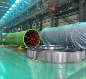
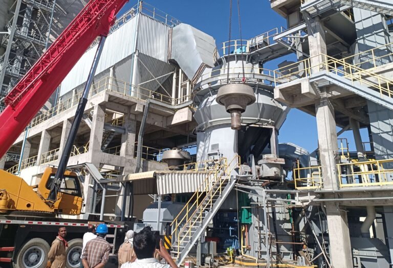
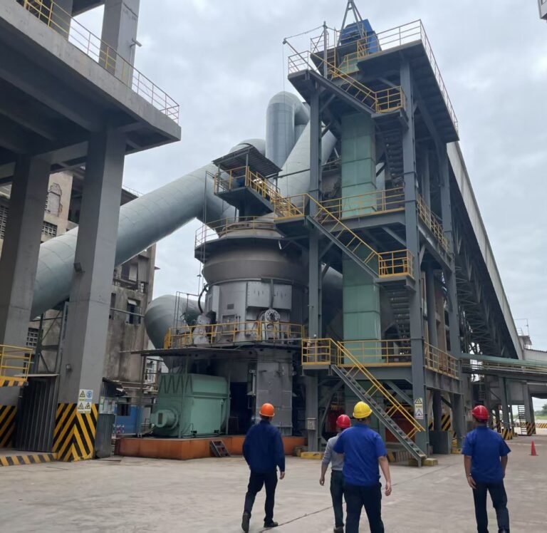
Introduction: Saudi Arabia UACC is a complete 6000T/D cement clinker production line. The project owner is UMM AL-QURA Cement Company and the consulting company is AUSTROPLAN. It includes all detailed surveys, designs, supplies, construction and commissioning from ore to cement packaging and delivery, including clinics, technical buildings, restaurants and other front-of-plant facilities. The project does not include the power plant and the dormitory area and mosque for cement plant workers and their families. The project is located in Saudi Arabia, Mecca region, between the highway from TAIF to Riyadh, about 120 kilometers away from TAIF, a larger city in Saudi Arabia, and about 7 kilometers away from the Jeddah-Mecca-Taif-Riyadh highway. The transportation is relatively convenient and will be completed and put into production in 2015.
Hoisting characteristics: The grinding disc is the heaviest single piece of equipment in the installation of the raw mill, with a weight of 100T, plus the weight of the hook of 3T, plus the weight of the wire rope hoist, the actual single lifting weight is 105T. The upper diameter of the equipment is 6000mm, the lower diameter is 3400mm, and the height is 2515mm. The installation plane height is +6.550m. When hoisting, first hoist the reducer into place, and then hoist the grinding disc. The reducer weighs about 98T. According to the on-site installation location and actual situation of the raw mill, it is decided to use the existing 250T crawler crane as the main hoisting tool. According to the performance table, it is decided to select a main arm of 22.5 meters, an operating radius of 12 meters, and a lifting capacity of about 106.2.
Step 1: Determine the position of the crane: According to the site conditions, the crane needs to enter the 12m operating radius. In view of the plane size of the vertical mill foundation, the crane crawler needs to enter the vertical mill foundation area. The actual vertical mill foundation plane height is + 1.00m. Before lifting, the crane operation position area needs to be filled with soil to be flush with the vertical mill foundation, and steel plates need to be laid after compaction to ensure the safe entry of the crane. In order to avoid the mill column, the parking position of the crane must comply with the data in the diagram, and the position can be pre-marked on the ground for easy positioning.
Step 2: Temporary placement of grinding disc and reducer: In order to facilitate lifting and avoid secondary handling, the grinding disc and reducer should be placed within the radius of the final lifting operation of the crane when unloading. When temporarily placed, the sleepers need to be padded with steel frames below to prevent the ground from settling and causing the equipment to tilt.
Step 3: Implementation of lifting operation: After the crane is successfully in place, operate according to the lifting operation diagram. This time, a 250T crawler crane was selected. The grinding disc weighs 100 tons. It adopts four-point lifting, equipped with 4 25-ton lifting rings and 4 2.5-inch steel wire ropes to meet the lifting capacity requirements.
Step 4: Wire rope safety factor calculation: The maximum weight of the lifting component is 105T, and 4 2.5-inch (diameter Φ63.5mm) wire ropes are selected, and their vertical breaking tension is 201Tf/mm. After calculation, the total breaking force of the wire rope is 903, and the minimum safety factor is 8.6, which meets the use requirements.
Precautious:
1. Isolate the lifting area and strictly prohibit unauthorized personnel from entering.
2. Use two sealing ropes to ensure the stability of the grinding disc during lifting.
3. When the lifting is not completed, personnel are not allowed to enter the range of the line connecting the crane and the center of the grinding disc, and can only stand on both sides of the crane mast.
4. Before lifting, fully check the safety facilities of the crane, especially the reliability of the winch brake and the hook limit.
5. During lifting, arrange a special person to monitor the sinking of the crane crawler in real time to maintain the flat ground.
6. Because the lifting weight exceeds the lifting capacity by 85%, it is necessary to pay close attention to factors such as weather, and suspend operations when the wind speed exceeds 8 meters/second.
Arrange a special person to command to prevent signal transmission errors.
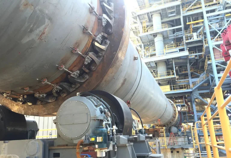
The grinding table dam ring of a vertical roller mill is usually located at the edge of the grinding disc. It is a ring-shaped component made of wear-resistant materials such as high-chromium cast iron. Its height and thickness vary depending on the model of the vertical mill. It mainly blocks the material, allowing the material to be ground on the grinding disc for sufficient time to prevent it from sliding off without being fully ground. At the same time, the material layer thickness can be controlled by adjusting the height, guiding the material to be evenly distributed on the grinding disc to form a specific flow path, and working in conjunction with the grinding roller, grinding disc liner and other components to improve the quality and efficiency of grinding and reduce equipment vibration.
The freely movable roller pairs are so arranged that with advancing wear they will vertically follow the wear profile. This ensures proper contact between the grinding elements and the material being ground.
Effective grinding performance, however, depends on the formation of an optimum bed of material. The level of this bed is determined by the height of the dam ring mounted on the outer grinding bowl edge. With advancing wear on the table liners (2) the grinding track depth, measured from the upper edge of the table liner, will naturally increase, so the thickness of the material bed on the grinding track will change accordingly.
When dealing with raw materials that have internal support characteristics that promote the formation of a very stable grinding bed, the increasing thickness of the material bed might become excessive and lead to an increased rolling resistance at the grinding rollers. This results in an increased specific power requirement for the grinding process. When grinding mill feed materials with the above–mentioned characteristics, the dam ring height must therefore be adjusted to match the progressing wear.
To adjust the dam ring height in a vertical roller mill, different dam ring heighteners must be selected to compensate for liner wear and maintain stable grinding performance. When the grinding track is new and has no wear, the dam ring should be set using the appropriate dam ring heightener (4.1) to ensure optimal grinding efficiency.
As the grinding track wears by 20-25% of its original thickness, the dam ring must be adjusted by replacing it with a dam ring heightener (4.2) to maintain the proper material layer and ensure consistent grinding performance.
When the grinding track experiences 40-50% wear, further adjustment is necessary by installing the dam ring heightener (4.3), which helps to stabilize the mill's operation and efficiency. The adjustment process must be carried out in accordance with the reference diagrams to ensure the correct positioning of the dam ring.
Properly adapting the dam ring height as wear progresses compensates for the reduced thickness of the table liners and ensures a constant material throughput, which is essential for maintaining the efficiency and performance of the mill. Regular inspections and timely adjustments are necessary to extend the service life of the grinding table and maintain optimal operation.
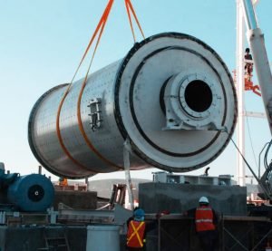
The grinding table can be transported either as separate components or as a fully assembled unit. It is crucial to use appropriate lifting equipment when unloading the grinding table from transport vehicles and transferring it to the storage area.
Upon arrival at the site, all parts must be inspected for transport damage and placed on wooden beams with adequate protection against rain, contamination, and mechanical damage. Under no circumstances should the parts be placed directly on the ground.
For long-term storage, the protective coating should be checked and repaired if necessary to maintain its integrity.
When performing electrical welding on any part of the machine, never allow the welding current to pass through plain bearings, antifriction bearings, movable connections, or measuring equipment, as this may cause damage.
The welding current return lead must always be directly connected to the part being welded.
Electric or autogenous welding and flame-cutting should never be carried out on the grinding track to prevent cracks from forming. Ground cables should also not be connected to the grinding track.
The grinding chamber is hot.There is mortal danger.
If you wish to enter the grinding chamber, you must wait until the mill has cooled down.
Before performing any repair work, switch off the power supply to all electrical components.
Ensure absolute cleanliness at all times during repair work in order to prevent dirt from entering the bearings, the drive units, the hydraulic system or other sensitive parts of the machine or plant.
Do not remove or open any flaps or protection devices before all rotating parts have stopped.
The installation of the vertical mill grinding table must strictly adhere to the specified tightening torques for bolts as indicated in the drawing. The process begins by carefully lowering the grinding table body onto the main gear unit. The bottom of the grinding table is then securely bolted to the driving flange of the main gear unit to ensure a stable connection.
Following this, the securing lugs are inserted into the designated bores of the grinding table body. Next, the wedge elements, along with their respective studs, are bolted onto the grinding table body. It is essential to ensure that the outer diameters of the wedge elements remain in full contact with the grinding table body to maintain structural integrity.
Once these components are in place, the table liner segments are positioned onto the grinding table body according to their marked sequence. Each table liner segment is shifted towards the outer rim until it makes full contact with the wedge elements. Further adjustments ensure that the table liner segments are also in complete contact with the securing lugs. If full contact is not achieved, plates of appropriate thickness must be inserted between the securing lugs and table liner segments and tack-welded into place using St 52-3 or an equivalent steel material.
After aligning the table liner segments, the grinding table cover is mounted onto the grinding table body without the upper plate. The table liner segments, together with the clamping plates, are then securely fastened to the grinding table body. Retaining brackets are placed beneath the clamping plates for additional outer fastening. The clamping plates for both inner and outer fastenings must be precisely aligned in a horizontal position. Expansion bolts with sleeves are inserted according to the drawing specifications and uniformly tightened to secure the assembly.
The next step involves tightening the fastening screws of the inner and outer securing lugs, followed by the installation of insulation materials. The retaining brackets are then welded to the upper plate ring of the insulation. Subsequently, the outer table ring is installed, and all gaps between the grinding table cover, outer table ring, and grinding track are filled with packing material.
The installation proceeds with mounting the dam rings and the upper plate of the grinding table cover. All joints between the table liner segments, dam ring, and grinding table cover must be tightly sealed using sealing cord. The sealing cord is further compressed by hammering it in with a flat steel bar to ensure a secure fit. Once completed, the dam ring heightener is installed.
Finally, the wear measurement template is adapted to the table liner profile. It is crucial that all measuring pins are flush with the upper edge of the template to ensure accurate wear assessment of the grinding track. By following these steps meticulously, the grinding table installation process is completed effectively, ensuring optimal performance and durability of the vertical mill.
After completing the assembly work, a thorough inspection of all plant components must be conducted before initiating the first test run. It is essential to ensure that no material remnants, tools, or assembly aids are left behind, as these could interfere with the proper operation of the grinding table.
One of the primary checks involves verifying that all bolted connections have been tightened according to the specified torque values outlined in the drawings. Any loose or improperly fastened bolts may lead to operational instability or mechanical failures during the test run.
Additionally, all joints on the grinding table surface must be adequately sealed using sealing cord. Proper sealing prevents material leakage and ensures that the grinding process operates efficiently without disruptions.
The adjustment of the dam ring must also be reviewed to confirm its correct positioning. An improperly set dam ring can lead to material flow inconsistencies, affecting the grinding efficiency and wear rate of the mill components.
Another critical inspection step involves measuring the grinding track using the designated wear measurement template. The measuring pins must be adjusted to ensure they are in full contact with the grinding track surface. This measurement provides a reference for monitoring wear over time and maintaining optimal grinding performance.
To systematically document these pre-test run inspections, refer to the measurement recording form available in section 9.1 of the technical drawings. By following these checks meticulously, the risk of operational issues during the test run can be minimized, ensuring the vertical roller mill functions as intended with maximum efficiency and durability.
To ensure the optimal performance and longevity of the vertical roller mill grinding table, regular maintenance is essential. Various components must be inspected, tightened, and replaced as needed to prevent failures and ensure smooth operation.
One of the critical maintenance tasks is retightening the expansion bolts (8.1) with the specified torque. When the table liners are new, this should be done after 30 to 50 operating hours. Subsequently, it should be repeated after 250 and 500 hours of operation, and then every six months. Any damaged expansion bolts must be replaced immediately to maintain structural integrity.
Additionally, all bolted connections must be retightened according to the specified torque values outlined in the drawings. This includes connections between the table body (1) and the gear unit, the dam ring heightener (4), and the table cover (5.1). This procedure is particularly crucial at the first startup and should be repeated every six months, as well as after 30 to 50 operating hours following any repair.
The sealing in the joints between the table liner segments, the dam ring, and the grinding table cover must be checked every six months. If necessary, sealing cord should be added and firmly compressed to ensure a proper seal, preventing material leakage and maintaining operational efficiency.
Another important aspect of maintenance is adjusting the dam ring heightener (4) as needed to match the wear progress of the grinding track. This adjustment helps maintain the proper material retention and grinding efficiency over time.
Finally, table liners (2) that have worn out must be replaced as required. The replacement of these liners is crucial to maintaining an even grinding surface and preventing excessive wear on other components.
By adhering to these maintenance practices, the vertical roller mill grinding table can operate efficiently and reliably, reducing the risk of unexpected breakdowns and ensuring a longer service life for the equipment.
The grinding table liners in a vertical roller mill must be replaced whenever wear inspections indicate that the limit values specified in the technical drawings (see section 9.1) have been reached. Additionally, any damage caused by improper use, such as breakage or displacement of the liners, necessitates immediate replacement to ensure safe and efficient operation. Failure to replace damaged liners can result in further deterioration of the grinding components and may cause operational disruptions.
Preparation for Replacement:
Before commencing the liner replacement process, ensure the mill is completely shut down, and all safety procedures are followed. Lockout and tagout procedures must be implemented to prevent accidental startup during maintenance. All necessary tools and equipment, such as hydraulic jacks, lifting gears, cast hooks, and appropriate wrenches, should be readily available. The work area must be clean and free from unnecessary obstructions to facilitate smooth operations.
Steps to Remove the Existing Table Liners
1. Remove One Roller Pair Unit:
To gain access to the grinding table, remove one of the roller pair units from the mill. The other roller unit should be lifted and securely fixed in place to ensure stability during the liner replacement.
2. Dismantle the Dam Ring Components:
Remove the dam ring heightener, dam rings, and the upper plate of the grinding table cover.
Carefully extract the packing material used in the joints to prevent contamination of the grinding surface.
3. Loosen and Remove Bolted Connections:
Loosen the expansion bolts and the studs securing the liners.
Remove the clamping plates to free the liners for extraction.
4. Disassemble the Wedge Elements:
Using available forcing screws, remove the wedge elements that hold the liners in place.
Once the wedges are removed, use a hydraulic jack to gently push the individual liner segments outward for easy extraction.
5. Lift and Remove the Table Liners:
Secure the table liner segments with cast hooks and use lifting equipment to safely extract them from the grinding table.
Rotate the grinding table using the auxiliary drive unit to position the respective liner segments correctly for removal.
Installation of New Table Liners
1. Positioning the New Liners:
Align the new table liner segments according to the markings to ensure they match the grinding table structure.
Lower them into place using lifting gears and position them securely on the table surface.
2. Securing the Liners:
Insert the wedge elements back into their designated slots and tighten them appropriately.
Reinstall the clamping plates and fasten them securely using the expansion bolts and studs with the specified torque values.
3. Reassemble the Dam Ring Components:
Reattach the dam ring heightener, dam rings, and grinding table cover.
Insert fresh packing material to seal any joints and prevent material leakage.
4. Final Inspection and Testing:
Ensure all bolts are tightened according to the specified torque values in the technical drawings.
Verify that the liners are firmly in place and properly aligned with the grinding track.
Conduct a thorough visual inspection to check for any installation errors.
Post-Installation Checks:
After the replacement process, conduct a test run to confirm that the mill is functioning correctly. Monitor for any unusual vibrations, misalignments, or material leaks. If necessary, make final adjustments to optimize grinding efficiency.
By following this structured approach, the grinding table liner replacement process can be carried out safely and effectively, ensuring prolonged mill operation and maintaining optimal grinding performance.
The grinding table of a vertical roller mill comprises several essential spare parts, each playing a crucial role in ensuring proper operation and longevity. The core component is the grinding table body, serving as the foundation for all other elements. Positioned on the grinding surface are the table liners, which provide protection against wear and tear. Surrounding the grinding table, the dam ring and its corresponding dam ring heighteners (available in multiple configurations) help control material flow and enhance grinding efficiency.
Additionally, the grinding table cover and outer table ring enclose the structure, while insulation materials provide necessary thermal protection. Various fastening components, including expansion bolts, clamping plates, sleeves, retaining brackets, studs, and fitted bolts, ensure that all parts remain securely in place during operation. Other critical elements such as wedge elements, securing lugs, and the fixing ring contribute to maintaining proper alignment and stability.
To further enhance safety and durability, the system incorporates a cover, a safety pin, and packing materials, which effectively seal joints and prevent material leakage. Each of these components is indispensable in maintaining the efficiency and performance of the grinding table in a vertical roller mill, ensuring smooth operation and prolonged service life.
Grinding disc diameter:
1. Material bed area and grinding capacity: The larger the diameter of the grinding disc, the larger the material bed area it carries, and the more material can be processed at the same time. Under the same number of grinding rollers and pressure conditions, a grinding disc with a larger diameter can accommodate more materials for grinding, making the grinding process more continuous and stable, thereby improving the grinding efficiency.
2. Material residence time and grinding effect: For grinding discs with larger diameters, the path for materials to move from the center to the edge is longer, and the residence time is relatively increased. This allows the material to have more time to contact the grinding roller and receive sufficient extrusion and grinding, which is conducive to improving the fineness and uniformity of the grinding, thereby improving the grinding efficiency.
3. Centrifugal force and material distribution: As the diameter of the grinding disc increases, the centrifugal force will also increase accordingly, which can make the material more evenly distributed in the edge area of the grinding disc, forming a more stable and uniform material bed. In this way, the force of the grinding roller on the material is more balanced, avoiding the situation of local over-grinding or under-grinding, and improving the grinding efficiency.
Grinding disc thickness:
Structural stability and bearing capacity: Properly increasing the thickness of the grinding disc can improve the structural strength and stability of the grinding disc, so that it can withstand greater grinding pressure and material weight. In high-load grinding operations, thick grinding discs are not easy to deform or damage, ensuring good cooperation between the grinding disc and the grinding roller, which is conducive to maintaining stable grinding efficiency.
Heat dissipation and temperature control: A large amount of heat will be generated during the grinding process. When the thickness of the grinding disc is large, its heat capacity is relatively large, which is conducive to heat dissipation and temperature control. A stable temperature environment can prevent the material from sticking and agglomerating due to overheating, ensure the fluidity and grinding effect of the material, and indirectly improve the grinding efficiency.
Energy transfer and loss: Thicker grinding discs are more stable when transmitting power, and the energy loss is relatively small. It can more effectively transfer the energy input by the motor to the grinding disc and the material during the grinding process, improve energy utilization, and thus improve grinding efficiency.
Material retaining ring height:
Material bed thickness and grinding effect: The height of the material retaining ring directly affects the thickness of the material bed on the grinding disc. Properly increasing the height of the retaining ring can form a thicker material bed on the grinding disc. A thicker material bed can increase the mutual extrusion and friction between materials, improve the grinding effect, and thus improve the grinding efficiency.
Material circulation and powder selection efficiency: The height of the retaining ring will affect the number of material cycles. If the retaining ring is too high, the material stays on the grinding disc for too long, which may lead to over-grinding, increase energy consumption and reduce grinding efficiency; if the retaining ring is too low, the material overflows the grinding disc too early, and the grinding is not sufficient, which will also affect the grinding efficiency. The appropriate height of the retaining ring can make the material achieve the best grinding effect and powder selection efficiency after a proper number of cycles of grinding on the grinding disc.
Airflow and material transportation: The height of the retaining ring will also affect the distribution of airflow in the mill and the material transportation effect. The appropriate height of the retaining ring can make the airflow form a reasonable flow field above the grinding disc, effectively blow up the ground material and transport it to the powder selector for classification, and improve the operating efficiency of the entire grinding system.
Material hardness:
For materials with lower hardness, such as limestone and gypsum, a relatively small diameter grinding disc can be selected. Usually, a diameter of about 2-3 meters can meet production needs. The thickness of the grinding disc can also be relatively thin, between 300-500 mm, which can not only ensure structural strength, but also reduce costs and equipment load. The height of the retaining ring is generally 100-150 mm to form a material bed of appropriate thickness for grinding.
For materials with higher hardness, such as iron ore and corundum, it is recommended to use a grinding disc with a larger diameter, such as 4-6 meters or even larger, to increase the grinding area and bearing capacity, disperse the grinding pressure, and reduce the wear of the grinding disc and grinding roller. The thickness of the grinding disc needs to be increased to 500-800 mm accordingly to improve the deformation resistance and wear resistance of the grinding disc. The height of the retaining ring can be appropriately increased to 150-200 mm to form a thicker material bed on the grinding disc and enhance the buffering and grinding effects.
Material particle size:
For materials with finer particle size, such as coal powder, the diameter of the grinding disc can be selected to be medium to small, 2.5-3.5 meters is more suitable, which is conducive to improving the grinding efficiency and controlling the fineness of the product. The thickness of the grinding disc is 400-600 mm, and the height of the retaining ring is 120-180 mm to ensure that the material has a proper residence time and grinding effect on the grinding disc.
For materials with larger particle size, such as large pieces of ore, a larger diameter grinding disc is required, such as 4-5 meters, to accommodate and process larger particles of materials, while increasing the contact area between the grinding disc and the material, and improving the crushing and grinding efficiency. The thickness of the grinding disc can be 600-800 mm, and the height of the retaining ring is 180-250 mm to prevent large particles from overflowing the grinding disc prematurely.
Material humidity:
For materials with low humidity, the selection of the grinding disc size mainly considers factors such as output and grinding efficiency. Generally, the appropriate grinding disc diameter, thickness and retaining ring height can be determined according to the hardness and particle size of the material.
Materials with high humidity: In order to prevent the material from sticking and agglomerating on the grinding disc, which will affect the grinding effect, a grinding disc with a larger diameter can be selected to increase the spreading area of the material, accelerate the evaporation of water and heat dissipation. The thickness of the grinding disc can be appropriately increased to increase the heat capacity of the grinding disc, which is helpful for drying the material. The height of the retaining ring can be appropriately reduced to 100-150 mm, so that the residence time of the material on the grinding disc is relatively shortened, and the possibility of material sticking is reduced.
Material output:
Low output demand: A small vertical mill can be selected, with a grinding disc diameter of about 1.5-2.5 meters, and the matching motor power is relatively small, which can meet the needs of small-scale production, and the equipment investment and operating costs are low.
High output demand: It is necessary to choose a large vertical mill, the grinding disc diameter is usually 3-6 meters or even larger, and it is equipped with a high-power motor and corresponding auxiliary equipment to improve production capacity and meet the requirements of large-scale production.
Function
1. Protect the grinding disc body
Anti-wear: During the operation of the vertical mill, the material moves continuously on the grinding disc, and the grinding roller crushes and grinds the material. During this process, there is strong friction between the grinding disc, the material and the grinding roller. As a direct contact component, the liner bears these frictions and wears, avoids direct wear of the grinding disc body, and greatly extends the service life of the grinding disc.
Anti-corrosion: If the material has a certain corrosiveness, the liner can isolate the material from the grinding disc, prevent the grinding disc from being corroded, and ensure the structural integrity and performance stability of the grinding disc.
2. Optimize the material grinding process
Promote the formation of the material bed: The reasonably designed surface shape and structure of the liner can help the material form a uniform and stable material bed on the grinding disc. For example, the texture or protrusions on the surface of the liner can make the materials squeeze and pile up better, forming a material bed with a certain thickness and strength, providing a good foundation for the effective crushing of the material by the grinding roller.
Guide the flow of materials: The shape and layout of the liner can guide the material to flow along a specific path on the grinding disc. For example, a specific angle or guide structure is set on the edge of the liner so that the material can flow orderly from the center of the grinding disc to the edge under the action of centrifugal force and grinding rollers, ensuring that the material can fully pass under the grinding roller and receive sufficient rolling and grinding.
Improve grinding effect: Different liner structures can provide different grinding environments for materials. Some liner surfaces are designed with special grooves or ribs. When the grinding roller rolls the material, these structures can subject the material to additional shearing and kneading, thereby improving the grinding effect, making the material more fully ground and the product particle size more uniform.
3. Easy maintenance and cost reduction
Convenient partial replacement: For split liner, when part of the liner is worn or damaged, only the damaged small liner needs to be replaced, instead of replacing the entire liner like the integral liner, which greatly reduces the maintenance workload and maintenance costs, shortens the equipment downtime, and improves the equipment's operating efficiency.
Targeted repair: The structure of the split liner makes it possible to select small liner plates of different materials or thicknesses for replacement according to the wear conditions of different positions of the grinding disc, thereby achieving targeted repair of the grinding disc wear and further improving the efficiency and economy of the liner.
Structural form
1. Integral lining
Construction features: The integral lining is a complete lining with a large size. It can usually cover the entire surface of the grinding disc or a large area of the grinding disc. The shape is generally compatible with the shape of the grinding disc, and most of them are large-area plate structures in the shape of a circle or a fan.
Installation method: It is fixed on the grinding disc by bolt connection or welding. During installation, the entire lining needs to be accurately installed at the predetermined position of the grinding disc to ensure a close fit with the grinding disc.
2. Split lining
Construction features: It is composed of multiple small linings, each of which has a relatively regular shape, generally a simple shape such as a fan or rectangle, and is relatively small in size, which is convenient for handling and installation.
Installation method: These small linings are spliced and installed on the grinding disc through specific installation structures, such as bolt connection, dovetail groove connection or slot connection, and can be installed in a targeted manner according to the wear conditions of different positions of the grinding disc.
1. MPS vertical mill grinding disc
Shape: The bowl-shaped grinding disc with arc groove is used. This shape is conducive to guiding the material to form a stable material bed on the grinding disc, so that the material can be better squeezed and sheared by the grinding roller during the grinding process.
Track: There is an arc groove track corresponding to the grinding roller on the grinding disc, which can make the contact between the grinding roller and the grinding disc closer, improve the grinding efficiency, and reduce the sliding and leakage of materials.
Material flow: The material flow on the disc surface is smooth, which can make the material evenly distributed on the grinding disc, avoid local accumulation of materials or too fast flow rate, and ensure the stability and uniformity of the grinding process.
2. ATOX vertical mill grinding disc
Shape: It is a flat track grinding disc with a relatively simple structure. The flat design makes the manufacturing and installation of the grinding disc more convenient, and it is also conducive to the rapid flow and dispersion of materials on the grinding disc.
Track: There is no special groove or raised track on the grinding disc. The grinding roller directly rolls and grinds the material on the plane. The material flows to the edge of the grinding disc under the action of centrifugal force, and the flow resistance is small.
Material flow: The material flows faster on the flat grinding disc, can quickly pass under the grinding roller to be ground, and then be carried by the airflow into the powder selection device, which is suitable for processing materials with good fluidity.
3. RM type vertical grinding disc
Shape: The cross section of the grinding disc is a bowl-shaped structure, with two circles of grooved tracks on the grinding disc, corresponding to the two groups of grinding rollers assembled by two narrow rollers, which can increase the number and time of material grinding and improve the grinding efficiency.
Track: The double track design allows the material to have more grinding paths on the grinding disc. The material is repeatedly crushed and ground by the grinding roller in the two circles of groove tracks, and can be more fully crushed and refined.
Material flow: The material flows in the double track, and a specific flow path is formed in the track through the action of the grinding roller, which is conducive to controlling the residence time and grinding degree of the material. The matching of the grinding roller and the track can be adjusted as needed to meet the grinding requirements of different materials.
4. Loesche mill (LM type) grinding disc
Shape: It adopts parallel grinding discs, and the surface of the grinding disc is a flat structure. It is used in conjunction with a frustum-shaped grinding roller. This structure can make the contact area between the grinding roller and the grinding disc larger, which can effectively transmit the grinding pressure and fully grind the material.
Track: There is no special track design. Relying on the angle and relative movement between the frustum-shaped grinding roller and the flat grinding disc, the material forms a natural flow and grinding area on the grinding disc. The material diffuses from the center to the edge of the grinding disc under the action of centrifugal force.
Material flow: The flow of materials on the flat grinding disc is relatively free, and it can be quickly distributed on the grinding disc and ground in contact with the grinding roller. It is suitable for processing various types of materials, especially for materials with small particle size and good grindability, with high grinding efficiency.


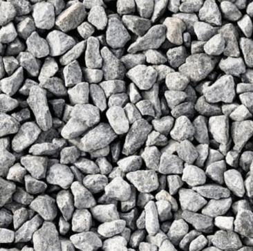
Designed for blast furnace slag grinding, widely used in cement production

In the cement production process, vertical mill discs are used to grind raw materials such as limestone, clay, and iron ore, and grind these block materials into fine powder for subsequent batching and calcination processes. At the same time, it is also used to grind cement clinker to produce cement products of different grades to ensure that the particle size and performance of cement meet the standard requirements.

In thermal power plants, vertical mill discs are used to grind coal powder. The raw coal is ground into fine coal powder through the vertical mill disc, and then sent to the boiler for combustion to provide heat energy for power generation. The grinding disc can accurately control the fineness and uniformity of the coal powder, improve combustion efficiency, and reduce energy consumption and pollutant emissions.
In mining and processing, vertical mill discs can be used to grind various ores, such as gold, copper, iron, etc. Grinding the mined ore into fine powder is convenient for subsequent mineral processing and metal extraction processes, and improves the recovery rate of ore and resource utilization.
Many raw materials and products in chemical production need to be ground. Vertical mill discs can be used to grind chemical raw materials such as calcium carbonate, talcum powder, kaolin, etc., to produce fine powders that meet the requirements of different chemical processes, which are used to manufacture chemical products such as plastics, rubber, coatings, inks, etc., to improve the performance and quality of products.
In the field of metallurgy, vertical mill discs are used to grind metallurgical auxiliary materials, such as limestone, dolomite, etc. These ground auxiliary materials play a role in adjusting the slag composition and promoting the removal of impurities in the process of steel smelting, thereby improving the quality and production efficiency of metallurgical products.

In addition to cement production, vertical mill discs are also used in the building materials industry to grind materials such as gypsum and quartz sand, and produce products such as building gypsum powder and quartz sand powder. These products are widely used in building decoration, wall materials, insulation materials and other fields.
In the process of ceramic production, vertical mill discs are used to grind ceramic raw materials, such as feldspar, quartz, clay, etc. Grinding these raw materials into fine powders with uniform particle size provides high-quality raw materials for subsequent ceramic body molding and firing, ensuring the texture and performance of ceramic products.
For the processing of non-metallic minerals such as graphite, mica, and diatomaceous earth, the vertical mill can grind these ores into powders of different finenesses to meet the application needs of non-metallic mineral products in multiple industries such as electronics, chemicals, and environmental protection, such as battery electrode materials, electronic insulation materials, adsorption materials, etc.

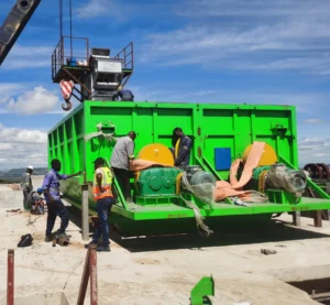
Understanding GGBS Production Lines: Essential Equipment, Benefits and Investment Insights
A GGBFS production line transforms blast furnace slag, a byproduct of steel production, into finely ground granulated slag.
February 07, 2025

What is Cement Production Lines: From Raw Material to Finished Product
A cement production line automates the manufacturing of cement, from raw material processing to packaging.
August 22, 2024
Raw Milling For Cement Meal and Clinker Grinding Plant: Ball mill Vs Vertical roller mill
Advanced mill technology for the grinding of cement raw meal and cement clinker for use in high-grade building materials.
February 19, 2025
You can get in touch with us through the following contact information
AddressNo. 2289 Huancheng South Road, Tongxiang, Jiaxing, Zhejiang Province, China. Zip code:314500
Please fill in the sales inquiry form and our sales representatives will be in touch shortly.